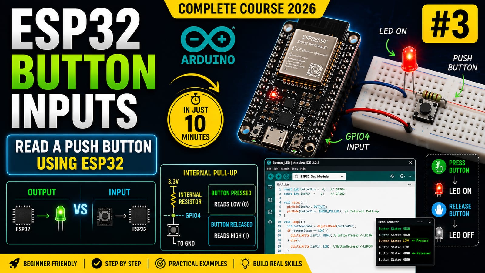
Introduction
So far, the ESP32 has been sending signals. In this lesson, we reverse the direction and teach the ESP32 to receive information from the outside world using a push button.
Digital inputs are used everywhere in embedded systems: buttons, switches, sensors, door contacts, limit switches, and many industrial signals all rely on the same basic idea.
Output vs input
When a GPIO pin is configured as an output, the ESP32 drives the pin HIGH or LOW.
When a GPIO pin is configured as an input, the ESP32 observes the voltage on that pin and reads it as HIGH or LOW.
In this project:
- GPIO2 controls an LED
- GPIO4 reads a button
The floating input problem
A digital input must have a defined voltage. If nothing is connected to the input, the pin can float. A floating input may randomly read HIGH or LOW because it is affected by electrical noise, nearby signals, and tiny leakage currents.
This is why button inputs need pull-up or pull-down resistors.
The interactive lab Pull-up and Pull-down Resistors shows how the input voltage changes when the button is pressed and released.
Pull-up vs pull-down
A pull-up resistor connects the input to 3.3V through a resistor. When the button is not pressed, the pin reads HIGH. When the button connects the pin to ground, the pin reads LOW.
A pull-down resistor connects the input to ground through a resistor. When the button is not pressed, the pin reads LOW. When the button connects the pin to 3.3V, the pin reads HIGH.
Both methods work. The important point is that the pin always has a defined default state.
Using the ESP32 internal pull-up
The ESP32 includes internal pull-up resistors that can be enabled in software. That means we do not need to add an external resistor for this beginner button circuit.
We enable it with:
pinMode(buttonPin, INPUT_PULLUP);With INPUT_PULLUP, the button logic is inverted:
- Released button reads HIGH
- Pressed button reads LOW
This is normal and expected.
Hardware required
- ESP32 DevKit
- Push button
- LED
- 220 ohm resistor
- Breadboard
- Jumper wires
Wiring
LED wiring:
GPIO2
  |
 LED
  |
220 ohm
  |
 GND
Button wiring:
GPIO4 ---- Push Button ---- GNDNo external pull-up resistor is required because the ESP32 internal pull-up is enabled in code.
Source code
const int ledPin = 2;
const int buttonPin = 4;

void setup()
{
    pinMode(ledPin, OUTPUT);
    pinMode(buttonPin, INPUT_PULLUP);
}

void loop()
{
    int buttonState = digitalRead(buttonPin);

    if (buttonState == LOW)
    {
        digitalWrite(ledPin, HIGH);
    }
    else
    {
        digitalWrite(ledPin, LOW);
    }
}
Code explanation
The LED pin is configured as an output:
pinMode(ledPin, OUTPUT);The button pin is configured as an input with the internal pull-up resistor enabled:
pinMode(buttonPin, INPUT_PULLUP);Then the code reads the button:
int buttonState = digitalRead(buttonPin);Because we use INPUT_PULLUP, a pressed button connects GPIO4 to ground, so the input becomes LOW. That is why the condition checks for LOW:
if (buttonState == LOW)When the button is pressed, the LED turns on. When the button is released, the LED turns off.
Common mistakes
If the button does not behave correctly, check:
- Button legs are placed across the breadboard gap
- One side of the button goes to GPIO4
- The other side goes to GND
- Code uses
INPUT_PULLUP, not plainINPUT - Logic checks for LOW when pressed
- ESP32 ground is connected to the circuit ground
Real engineering use cases
Digital inputs are used for:
- User buttons
- Limit switches
- Door sensors
- Motion detector outputs
- Emergency stop loops
- Mode selection switches
- Machine state feedback
Once you understand this button circuit, you can read many other digital devices.
Engineering challenge
Modify the project so the LED toggles every time the button is pressed instead of only staying on while the button is held down. This introduces the idea of state, edge detection, and eventually debouncing.
Next lesson
In the next lesson, we will use PWM to control LED brightness instead of simply turning it fully on or fully off.