Introduction
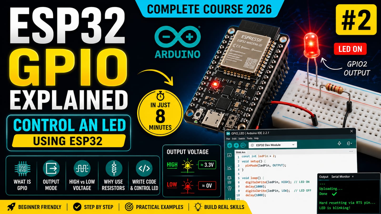
GPIO is one of the most important ideas in embedded systems. It is how a microcontroller talks to the outside world. In this lesson, we will use an ESP32 GPIO pin as an output and control an external LED.
This may look like a small project, but the concept scales directly to relays, motor drivers, buzzers, displays, indicators, and industrial control signals.
What is GPIO?
GPIO stands for General Purpose Input Output. A GPIO pin can be configured by software to either read a signal or send a signal.
In this lesson, we use GPIO2 as an output. That means the ESP32 controls the voltage on that pin.
When the pin is HIGH, it outputs approximately 3.3 volts. When the pin is LOW, it outputs approximately 0 volts.
HIGH and LOW
Digital output has two main states:
HIGH: the pin is driven to about 3.3VLOW: the pin is driven to 0V
By switching between these two states, the ESP32 can turn simple devices on and off.
For a deeper visual explanation, open the interactive lab: GPIO HIGH and LOW.
Why the LED needs a resistor
An LED is not like a normal resistor. Once it starts conducting, current can rise quickly. If we connect an LED directly between GPIO and ground, too much current may flow.
A current-limiting resistor reduces the current to a safe level.
For this beginner circuit, a 220 ohm resistor is a common choice.
You can explore the relationship between voltage, resistance, and current in the interactive lab: Current Through a Resistor.
Hardware required
- ESP32 DevKit
- LED
- 220 ohm resistor
- Breadboard
- Jumper wires
- USB cable
Wiring
Connect the LED and resistor like this:
GPIO2
  |
 LED
  |
220 ohm
  |
 GND
The longer LED leg is usually the positive side. The shorter leg is usually the negative side. If the LED does not turn on, check the polarity before changing the code.
Source code
const int ledPin = 2;

void setup()
{
    pinMode(ledPin, OUTPUT);
}

void loop()
{
    digitalWrite(ledPin, HIGH);
    delay(1000);

    digitalWrite(ledPin, LOW);
    delay(1000);
}
Code explanation
First, we store the pin number:
const int ledPin = 2;This makes the code easier to change later. If we move the LED to another GPIO pin, we only need to update one line.
Inside setup(), we configure the pin:
pinMode(ledPin, OUTPUT);This tells the ESP32 that GPIO2 will send electrical signals.
Inside loop(), we turn the LED on:
digitalWrite(ledPin, HIGH);Then we wait one second:
delay(1000);Then we turn the LED off:
digitalWrite(ledPin, LOW);Because loop() repeats forever, the LED continues blinking.
Testing
Upload the code to the ESP32. The LED should turn on for one second, turn off for one second, and repeat.
If it does not work, check:
- LED polarity
- Resistor connection
- GPIO number in the code
- Breadboard row alignment
- Ground connection
- Correct board and port in Arduino IDE
Real engineering use cases
The same GPIO output idea is used for:
- Relay control
- Motor enable pins
- Buzzers
- Status LEDs
- Display control pins
- Digital control lines in industrial equipment
The ESP32 pin often does not power large devices directly. Instead, it sends a control signal to another circuit such as a transistor, MOSFET, relay module, or motor driver.
Next lesson
Now that the ESP32 can send signals, the next step is receiving signals. In the next lesson, we will read a push button using INPUT_PULLUP.